ANTHONY NISTOR // DRONE

Custom Quadcopter Flight Controller

An Arduino Nano, a motion sensor, and a radio receiver became a custom flight-controller board for a printed-and-tube quadcopter.

// SYSTEM ARCHITECTURE

How the Aircraft is Controlled

The control path was drawn before the airframe was closed up. A radio sets the sticks, the Nano mixes those commands with motion from the sensor, and four motor outputs drive the corners.

  • Radio and Motion A RadioLink R8EF receiver supplies pitch, roll, yaw, and throttle. An MPU-6050 reports motion over I2C.
  • Four Motor Channels Front left, front right, back left, and back right each have their own signal out to an ESC.
  • From Prototype to PCB The first controller was point-to-point on perfboard. The flight board that replaced it is labeled Drone 1.0 and signed Anthony Nistor.
FLIGHT_CONTROL.LOG ACTIVE
1. RECEIVER

Pitch, roll, yaw, throttle, and auxiliary channels

R8EF
↓ Stick and motion data
2. NANO + IMU

Arduino Nano with MPU-6050 on I2C

MIX
↓ Four drive signals
3. MOTOR OUTPUTS

One command for each corner of the frame

TO ESC
// CONTROL SCHEMATIC

Flight Controller Wiring

The schematic maps the battery, the motion sensor, and the four ESC outputs onto the Nano.

FLIGHT_CONTROLLER_SCHEMATIC.PNGDRONE 1.0

Nano, IMU, and Four Corners

An 11.1 V lithium pack feeds the craft. The MPU-6050 sits on the five-volt logic rail. Motor lines leave the Nano for the front-left, front-right, back-left, and back-right ESCs.

// HARDWARE & SOFTWARE

System Component Breakdown

01

Arduino Nano

The flight computer, first on perfboard and then on the custom board.

02

MPU-6050

Six-axis motion sensor read over I2C for attitude.

03

R8EF Receiver

RadioLink receiver that brings the pilot’s channels into the controller.

04

Airframe

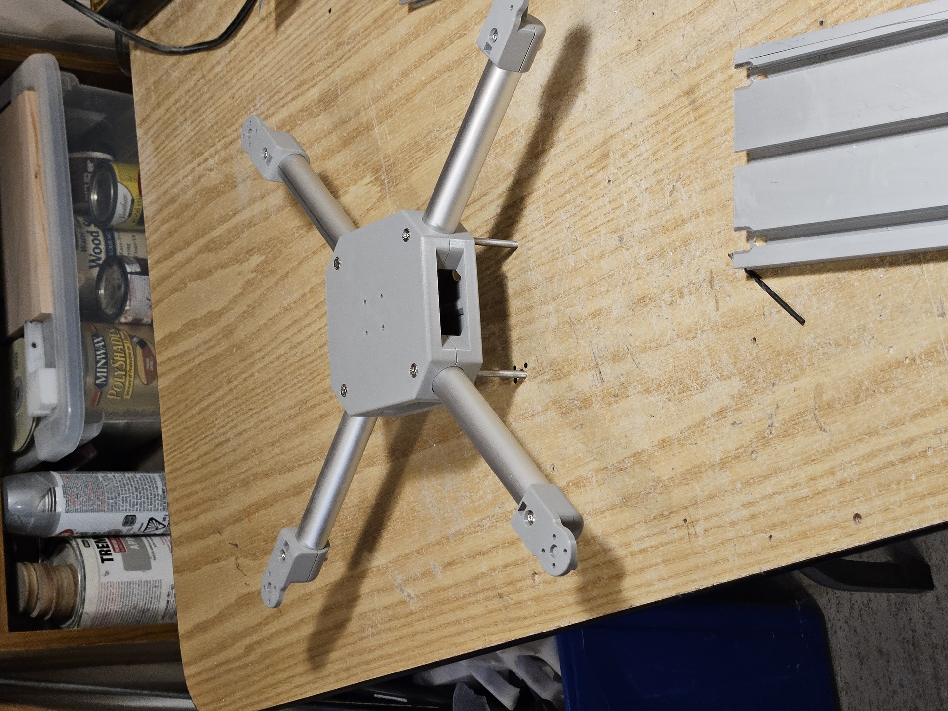
Olive printed center pod and motor mounts on aluminum arms, with a brushless motor at each corner.

// PROJECT MEDIA

Video Demonstration & Photos

The assembled quad, the hand-wired prototype, and the finished flight board.

AIRFRAME_TEST.MP4 BENCH / FLIGHT

Assembled Airframe Test

A recording from the completed quad: printed center, tube arms, and four motors. Later clips in the project folder continue the same test series.
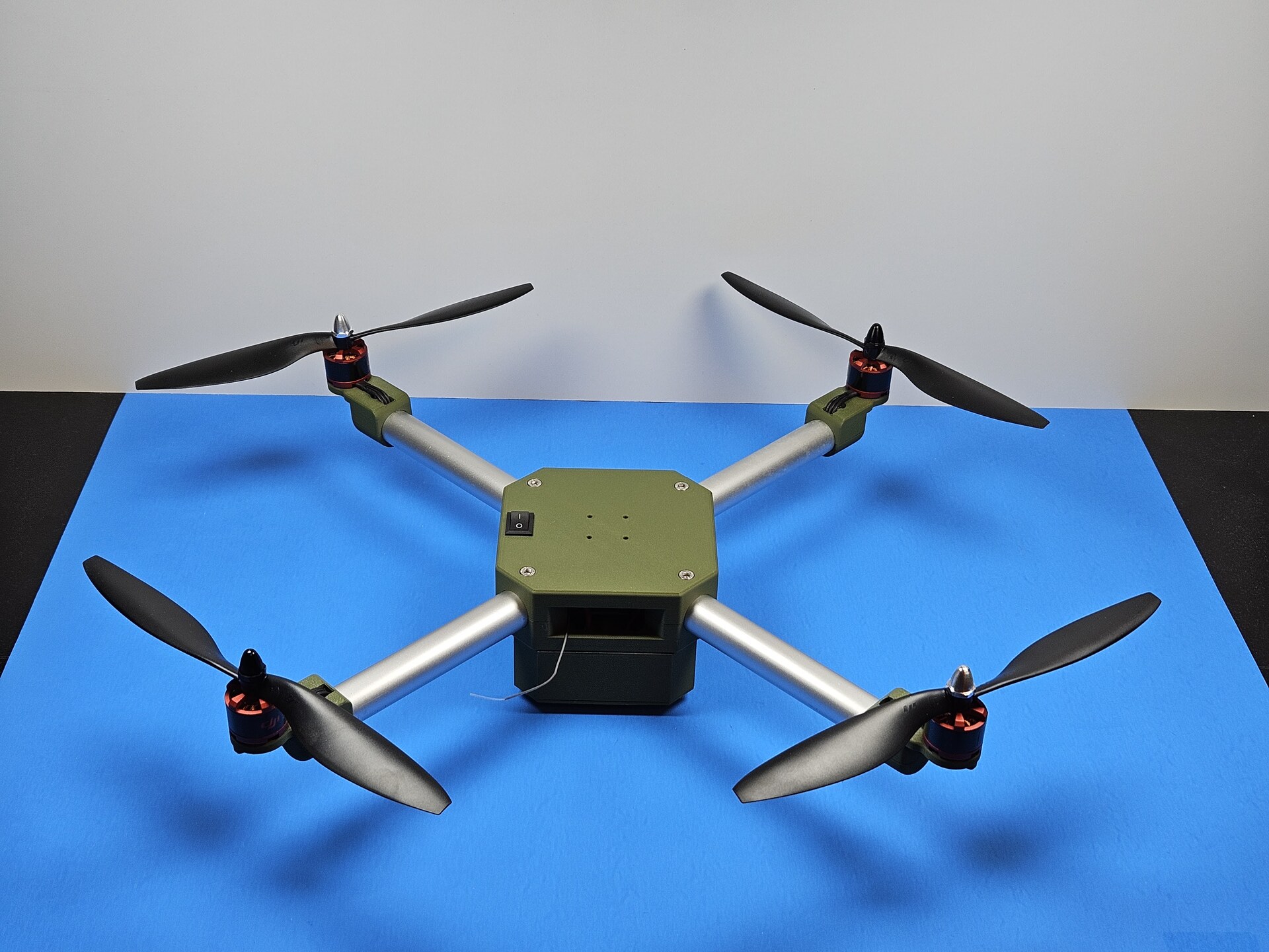
Assembled Quad
CLICK TO ENLARGE

Assembled Quad

Four motors on tube arms around the olive printed center pod.
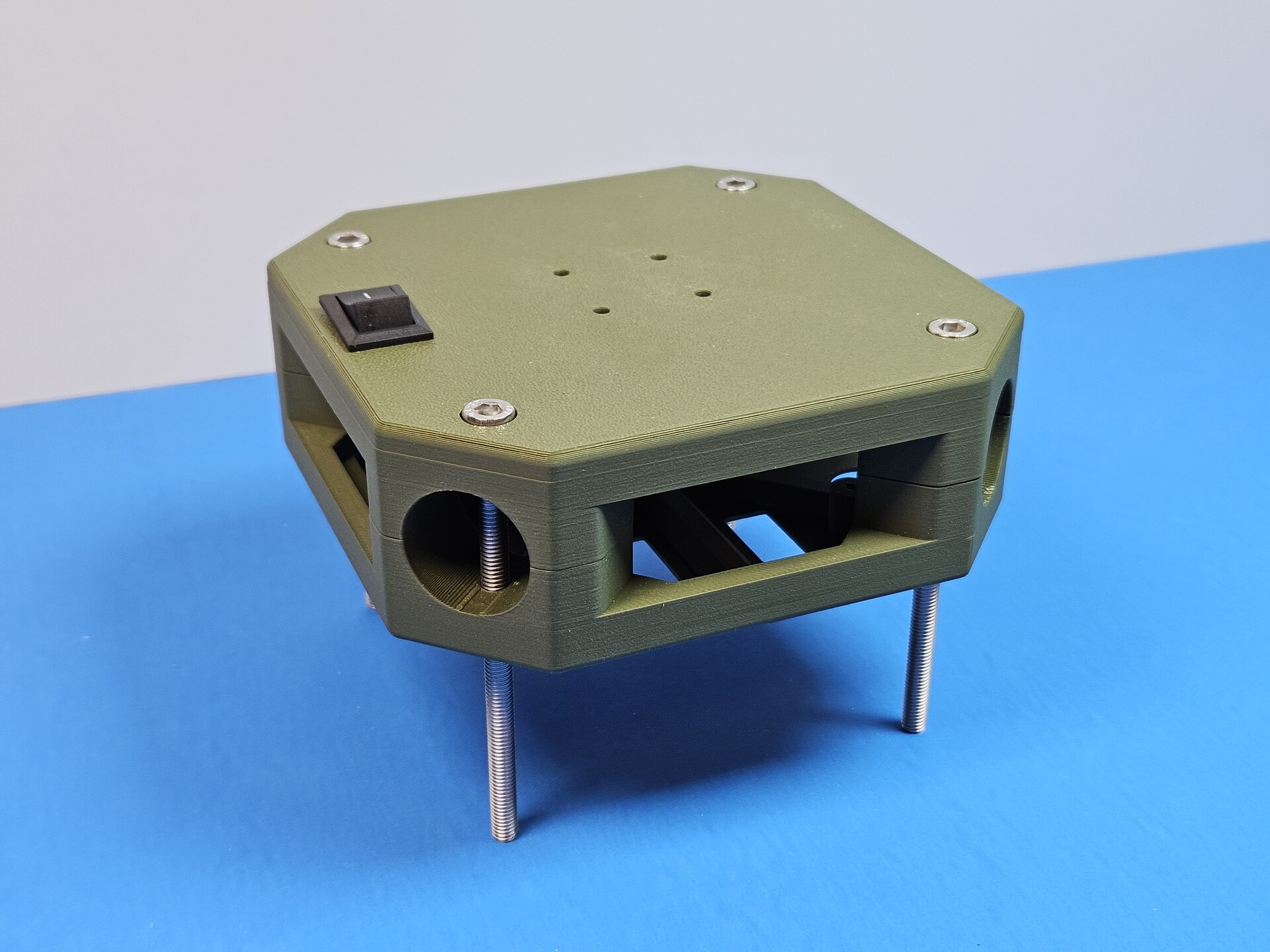
Center Pod
CLICK TO ENLARGE

Center Pod

Printed body with the power switch, arm sockets, and standoffs.
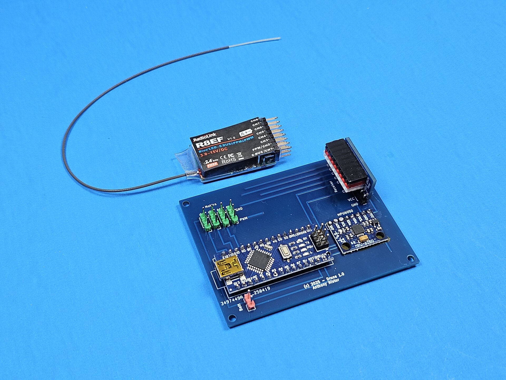
Flight PCB
CLICK TO ENLARGE

Flight PCB

The manufactured Drone 1.0 board beside the R8EF receiver.
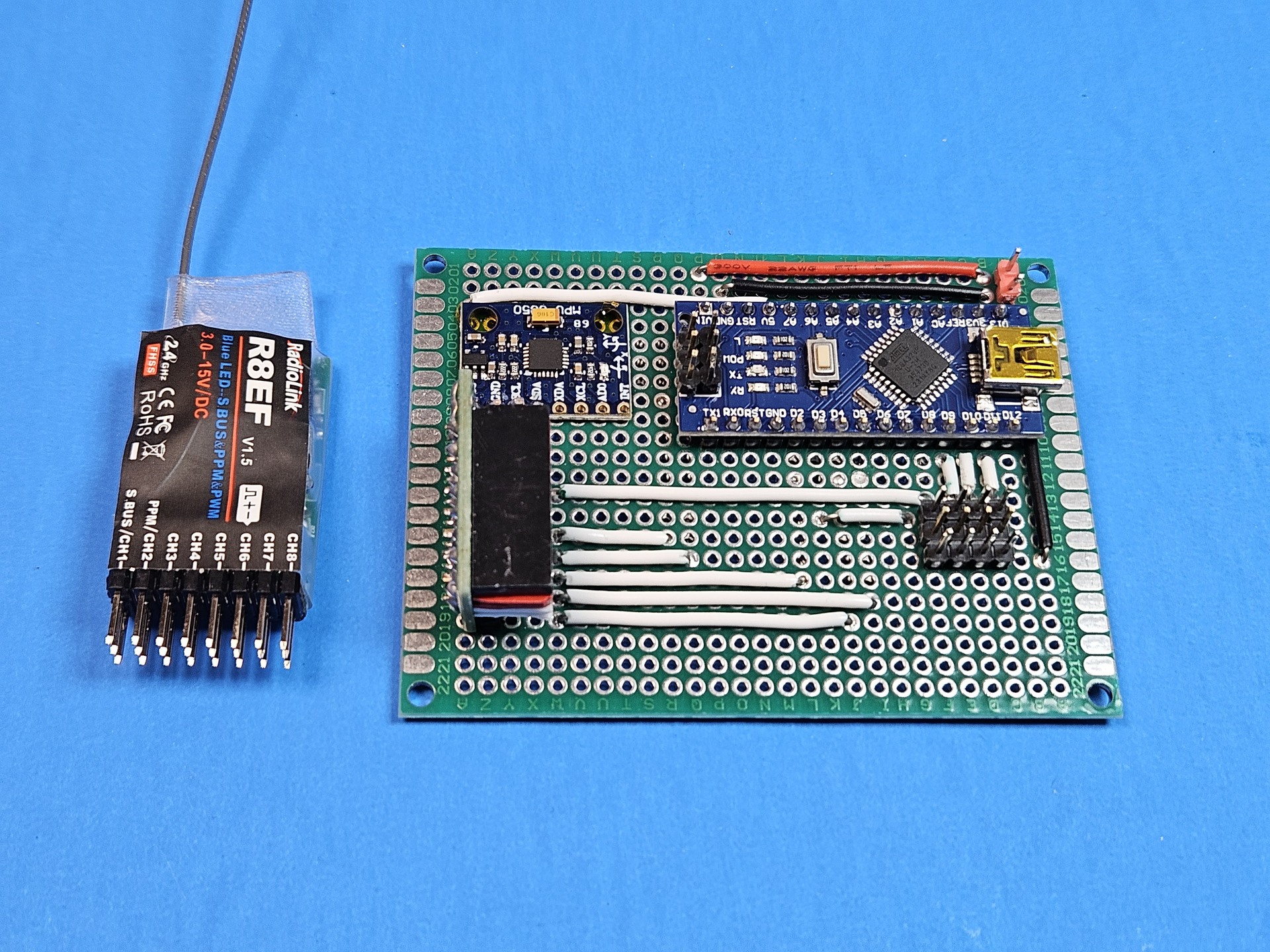
Perfboard Prototype
CLICK TO ENLARGE

Perfboard Prototype

The first controller, wired by hand before the PCB replaced it.
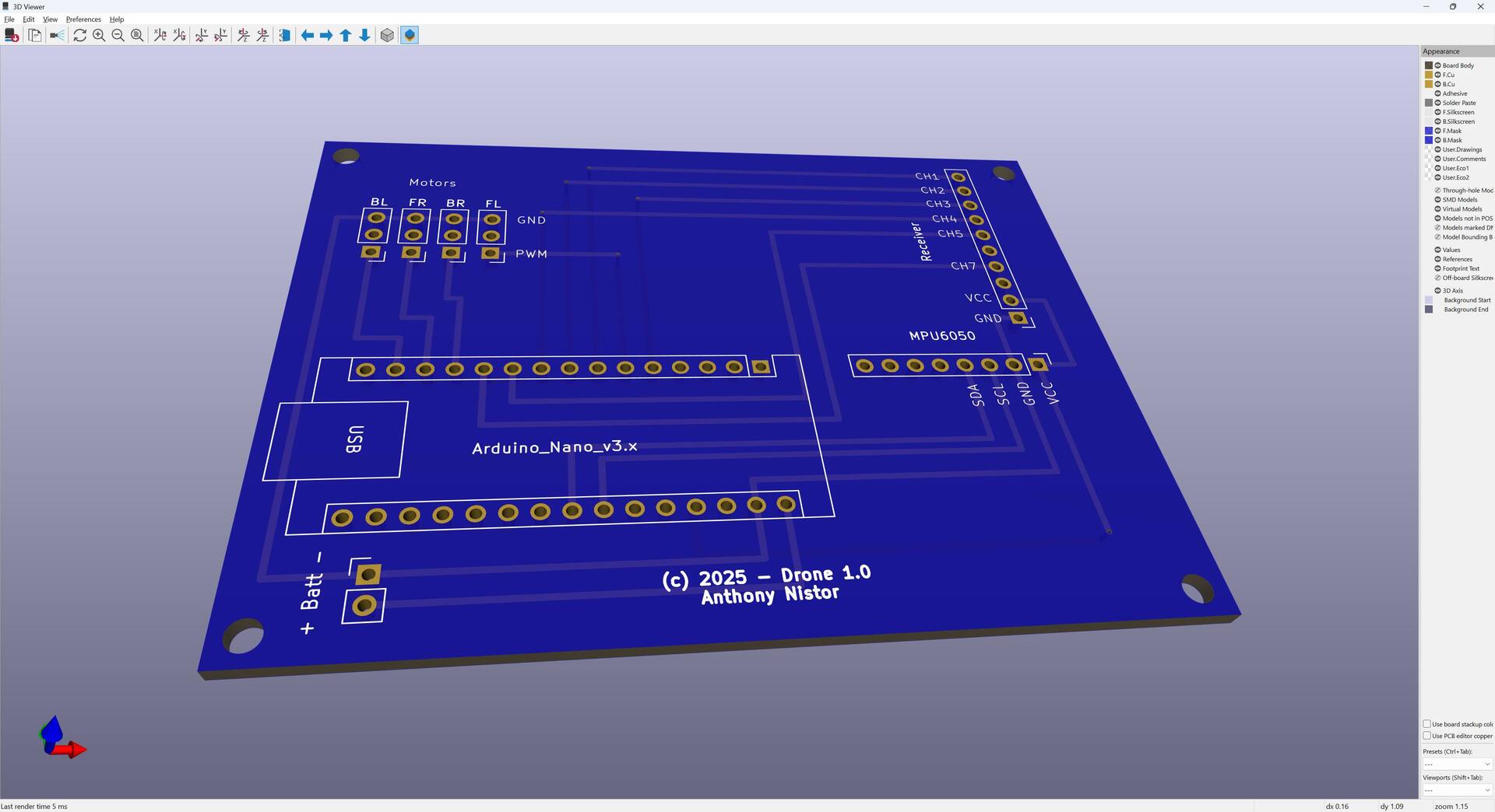
Board Render
CLICK TO ENLARGE

Board Render

KiCad view of the board signed Anthony Nistor, Drone 1.0.

Airframe CAD
CLICK TO ENLARGE

Airframe CAD

Center pod, four arms, and motor mounts in FreeCAD.
// SLIDESHOW

All Project Pictures

66 photographs and drawings from this build.

20250406_122621.jpg 1 / 66
20250406_122621.jpg
// TECHNICAL SPECIFICATIONS

System Parameters & Metrics

PARAMETER SPECIFICATION / VALUE
Flight Computer Arduino Nano
Motion Sensor MPU-6050 over I2C
Receiver RadioLink R8EF
Motor Outputs Front left, front right, back left, back right
Battery 3-cell lithium pack, 11.1 V on the schematic
Controller Board Custom PCB, Drone 1.0, Anthony Nistor
Airframe Printed center and mounts, aluminum tube arms